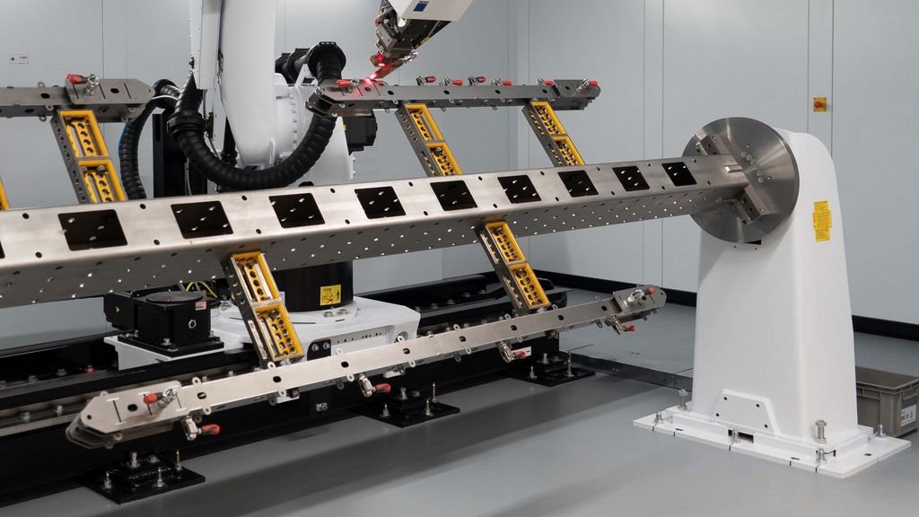
Welding Robot and Automated Flipping Fixture
To integrate a welding robot with an automated tilting fixture, first calculate the robot payload (≥1.2× gun + wire + fixture) and reach (≥half part length + 200 mm). Size the positioner torque T = 1.5–2×(m g rG + J α), keep inertia ratio ≤5 and deflection ≤L/1000. Link both via EtherCAT for 7-axis coordinated motion, maintain torch angle 30°±5° and stick-out 15±1 mm. Reserve 20 % safety margins, use high-stiffness bases and pre-loaded bearings, and validate with 200 idle cycles plus 8 h full-load weld; aim for ≥98 % first-pass NDT to avoid rework.
I. Overall Design Flow (concurrent design, cross-verification)
- Break down the welding process
a. Weld type (fillet / groove / girth), leg length, plate thickness t, deposition rate Vd.
b. Welding-position share: flat 60 %, vertical 25 %, overhead 15 % → robot must have full-pose interpolation.
c. Takt time = yearly output / (work-hours·3600 · uptime); target Takt ≤ 1.15 × theoretical cycle. - Work-piece physical data
Mass m, COG coordinates (x,y,z), inertia J, envelope L×W×H, weld-distribution solid angle α. - Parallel selection of robot & positioner
First estimate robot “must-reach radius Rmin” and “must-carry mass Mmin”, then estimate positioner “must-turn torque Tmin”; iterate twice to converge.
II. Robot Sizing Calculations
- Payload margin
Mpay = mgun + mwire + mfixture + mconsumables
Mrobot ≥ 1.2 Mpay (continuous arc) or ≥ 1.4 Mpay (pulsed high-current, heavy spike)[3^]. - Reach
Rreach ≥ Lpart/2 + Δ (torch 150 mm + clearance 50 mm)
For both-side welds check 180° base offset; otherwise add 7th-axis rail or second robot. - Speed & acceleration
Typical: idle 1.5 m s⁻¹, weld 5–12 mm s⁻¹ (MAG) / 10–40 mm s⁻¹ (laser).
Acceleration a = 0.3–0.5 g (full load) for cycle-time estimate.
Servo inertia ratio: Jload/Jmotor ≤ 5, otherwise gearbox needed[5^]. - Repeatability
±0.05 mm for arc welding; ±0.02 mm for laser; ±0.01 mm for remote laser scanner[3^]. - Example
Work-piece 1.2 m × 0.8 m × 0.4 m, 80 kg; torch + wire 18 kg; fixture 12 kg.
→ Mpay = 110 kg → pick 150 kg robot (36 % margin).
→ Rreach = 0.6 + 0.2 = 0.8 m → 2010 mm arm 6-axis model covers.
III. Automated Turning Fixture (Positioner) Calculations
- Tilting torque
T = m·g·rG + Σ(Ji·α) + Tfriction
rG = distance COG to axis; α = max angular accel (0.2–0.4 rad s⁻²);
Tfriction = 5–8 % loss from bearing/reducer catalogue.
Safety factor K = 1.5–2.0; final Tmotor ≥ K·T[1^]. - Quick inertia estimate
Rectangular block about centre: J = m/12·(a²+b²);
About offset axis: J′ = J + m·d².
SolidWorks mass properties give exact value for check. - Drive comparison
- Servo + precision gearbox: repeatability ≤ ±0.05°, good for multi-pass & laser.
- Hydraulic: high torque, low cost, accuracy ±0.3°, heavy rough parts only.
- Pneumatic: 90°/180° index, fast, ±0.5°, thin small parts[1^].
- Structural stiffness
Max deflection δ ≤ L/1000 under full load;
Q355 square tube 200×200×8 mm usually OK up to 2 t part[1^]. - Example continued
Same 80 kg part, COG offset 120 mm, 180° tilt in 2 s.
→ T = 80·9.81·0.12 + 80·0.12²·0.3 + 5 % ≈ 110 Nm
→ Tmotor ≥ 1.5·110 = 165 Nm
Select 200 Nm servo gearbox (i = 100, 2 kW motor, 2.4 Nm rated) – OK.
IV. Interface & Coordinated Control
- Mechanical
- Quick-change flange: robot side ISO 9409-1-125; fixture side Ø12 h6 pilot, repeatability <0.02 mm.
- Table: 16 mm steel plate, M16 holes 50×50 grid, flatness 0.1/1000.
- Electrical
- Both robot and positioner on EtherCAT, 4 ms cycle, synchronized interpolation.
- Safety: dual-channel E-stop, door switches, light curtain Cat. 3 / PL e; servo brake on positioner.
- Process coordination
- 7-axis interpolation (6 robot + 1 positioner) keeps torch angle 30°±5°, stick-out 15 mm±1 mm.
- Laser seam tracker 100 Hz, compensates ±1 mm thermal distortion in X-Z plane.
V. Commissioning & Acceptance Checklist
- 200 idle cycles, no alarm, repeatability ≤ 0.05 mm (robot) / ≤ 0.05° (positioner).
- 8 h continuous weld at 1.2 × load, motor ΔT ≤ 60 K, reducer housing ≤ 50 °C.
- First-pass NDT acceptance ≥ 98 %; repairs not allowed within 100 mm on same seam.
- Documentation: 3D STEP, 2D PDF, BOM, CE risk assessment, spare-part list.
VI. Field Pitfalls & Rules of Thumb
- Weak robot base → 6 Hz chatter gives “saw-tooth” bead; base mass ≥ robot mass.
- Positioner bearing clearance → stick-out varies in overhead weld → porosity; use crossed-roller or pre-loaded bearing.
- Servo inertia ratio >5 → overshoot at start, bead “nose”; add gearbox or lower accel.
- Cable/tube wrap ignored → for >360° tilt use hollow-shaft slip ring.
- Magnetic clamp residual → demagnetisation >350 °C; use high-temp magnets or mechanical backup.
One-sentence takeaway
“Size torque & inertia first, leave 20 % margin; synchronize positioner and robot via EtherCAT, simulate stiffness & accuracy together, and you will start up without rework.”