Detailed Analysis of the Structure, Assembly and Testing Process of Gasoline Engines for Portable Generators
Gasoline engines for portable generators belong to small single-cylinder reciprocating piston internal combustion engines, with core characteristics of light weight, low displacement (mainstream 50~400cc) and high adaptability, which are suitable for the constant-speed power generation needs of generators. In terms of structure, they simplify the complex systems of automotive gasoline engines and enhance reliability and portability; their assembly process follows the principle of “precision assembly and strict control”, and the testing process focuses on four core dimensions: power performance, power generation adaptability, reliability, and emission & noise. They are the key link to ensure the overall performance of portable generators. The following is a detailed analysis from three aspects: structure, assembly process and testing process.
I. Core Structure of Gasoline Engines for Portable Generators (mainly single-cylinder, air-cooled accounts for more than 99%)
Gasoline engines for portable generators all adopt air-cooled single-cylinder four-stroke (a small number of small-displacement ones are two-stroke, which are gradually eliminated). According to the valve timing method, they are divided into overhead valve (OHV) and overhead camshaft (OHC). Among them, the OHV structure is simpler and easier to maintain, making it the mainstream choice for portable generators. The overall structure can be divided into eight core parts: engine block assembly, crankshaft connecting rod mechanism, valve train, fuel supply system, ignition system, cooling system, lubrication system and starting system. Each part is designed with light weight and integration for portable scenarios, without complex auxiliary systems.
(I) Engine Block Assembly: The Foundation of the Whole Machine, Bearing Core Moving Parts
1. Cylinder Block + Cylinder Head: Most adopt die-cast aluminum alloy material (replacing cast iron, reducing weight by more than 60%). A cast iron cylinder liner is embedded in the cylinder block to improve wear resistance; the outer walls of the cylinder block and cylinder head of air-cooled models are cast with dense cooling fins, with a fin spacing of 8~12mm, adapting to the forced air-cooled airflow of the generator fan; the cylinder head integrates intake port, exhaust port and spark plug mounting hole, and the OHV model also integrates the valve chamber without a complex cylinder head cover.
2. Crankcase: It is connected with the cylinder block by integral die-casting or split bolt connection. The split type is convenient for assembly, and the integral type improves rigidity; the crankcase is processed with crankshaft bearing seats and lubricating oil channels, and the bottom is equipped with an oil pan (small engines have an integrated oil groove without an independent oil pan). The oil level is detected by a simple oil dipstick, adapting to the inclined use demand of portable movement (short-term inclination does not affect lubrication).
3. End Covers and Seals: Sealed end covers are installed at the front and rear ends of the crankshaft, equipped with nitrile rubber oil seals to prevent oil leakage and dust entry; thin rubber gaskets or sealants are used on each joint surface to simplify assembly.
(II) Crankshaft Connecting Rod Mechanism: Converting Reciprocating Motion into Rotational Motion, Core Power Output Component
1. Piston Assembly: The piston is die-cast aluminum alloy, with a flat top or shallow concave top (adapting to the homogeneous combustion of gasoline engines, without complex combustion chamber design). The piston rings are 2 compression rings + 1 oil ring. The compression rings adopt chrome plating process, and the oil ring is a steel strip combined type, adapting to the sealing demand of low speed (3000/3600rpm constant speed, the mainstream power generation speed of generators).
2. Connecting Rod: Adopt die-forged steel material, the rod body is designed with light-weight punching, and the two ends are bronze bushings (small end) and needle bearings (big end), adapting to the low-load and constant-speed motion characteristics without connecting rod bearings (simplified structure).
3. Crankshaft: Adopt ductile iron die forging or cold heading forming, single-throw crankshaft (single-cylinder). Both ends are processed with flywheel mounting surface and generator connecting flange (core adaptive structure). The flange is equipped with positioning pins and fastening bolts to ensure the coaxiality with the generator rotor (coaxiality error ≤ 0.05mm) and avoid power generation vibration; the crankshaft is processed with eccentric oil channels to supply oil to the connecting rod and main journal.
4. Flywheel: Cast iron material, which is not only an inertial energy storage component, but also integrates flywheel ring gear (suitable for electric start) and cooling fan blades (core of air cooling). The fan blades are centrifugal, generating forced airflow to blow the cooling fins when rotating. Some flywheels also integrate ignition signal trigger teeth (adapting to the ignition system) to achieve integrated design.
(III) Valve Train: Controlling Intake and Exhaust Timing, Ensuring Combustion Efficiency
The mainstream is OHV overhead valve type, with simple structure and low failure rate. It is composed of valve group and valve transmission group, without complex timing belt/chain tensioning mechanism:
1. Valve Group: 1~2 intake valves and 1~2 exhaust valves (1 intake and 1 exhaust for small displacement, 2 intake and 2 exhaust for large displacement). The valve stem is alloy steel, the valve seat insert is embedded in the cylinder head, equipped with valve spring, valve guide and valve oil seal to ensure sealing and smooth movement.
2. Valve Transmission Group: The camshaft is driven by the timing gear on the crankshaft. The camshaft pushes the tappet and push rod, and then drives the rocker arm to open and close the valve; the timing gear is helical to reduce transmission noise. The valve timing is a fixed value (no variable timing, simplified structure), adapting to the 3000/3600rpm constant speed demand without wide speed adaptation.
(IV) Fuel Supply System: Simple and Reliable, Adapting to Constant Speed and Low Load
There is no electronic fuel injection system of automotive gasoline engines, all are carburetor type (electronically controlled carburetor/small EFI electronic fuel injection system is adapted for national IV and above emissions). It has simple structure, low cost and easy maintenance, adapting to the field use demand of portable scenarios:
1. Core Components: Carburetor (mainly float type), fuel tank, fuel switch, fuel filter, intake pipe and muffler; the fuel tank is plastic material (light weight), with a capacity of 1~10L, equipped with fuel filter screen and oil level indicator; the muffler is impedance composite type, with noise reduction and heat insulation treatment (surface temperature ≤ 200℃).
2. Adaptive Design: The carburetor integrates idle speed adjusting screw and main jet adjusting screw, which can accurately adjust the air-fuel ratio (ideal air-fuel ratio 14.7:1) under 3000/3600rpm constant speed condition to ensure the power stability during power generation; the intake pipe is rubber + metal composite pipe to absorb vibration and prevent air leakage.
(V) Ignition System: Contactless, Reliable Ignition, Adapting to Low Speed and Constant Speed
Adopt CDI capacitor discharge ignition system (contactless magneto type), without the wear problem of traditional contact type, with stable ignition energy, which is the standard configuration of small gasoline engines:
1. Core Components: Magneto (integrated in the flywheel, generating high-voltage electricity when the crankshaft rotates), CDI igniter (electronic control module, miniaturized integrated), high-voltage coil and spark plug; the spark plug is a special small spark plug (such as NGK C7HSA), with a gap of 0.6~0.8mm, adapting to low-speed ignition demand.
2. Working Characteristics: The ignition advance angle is a fixed value (10~15° BTDC), determined by the position of the magneto trigger tooth, without electronic control advance angle adjustment, simplifying the structure and meeting the ignition demand of constant speed power generation.
(VI) Cooling System: Forced Air Cooling, No Liquid Cooling Circuit, Extreme Simplification
Gasoline engines for portable generators have no water cooling system (no water pump, water tank or water pipe), all are flywheel fan forced air cooling, which is their most prominent structural feature:
1. Cooling Process: When the flywheel rotates, the fan blades generate axial forced airflow, which first blows the cooling fins of the cylinder block, then the cooling fins of the cylinder head, and finally is discharged through the muffler; the airflow velocity is ≥ 10m/s, ensuring that the cylinder head temperature is ≤ 250℃ and the cylinder block temperature is ≤ 220℃ when working at full load of 3600rpm.
2. Auxiliary Components: An air guide cover (plastic material) is provided to concentrate the fan airflow to the cooling fins, prevent airflow dispersion and improve cooling efficiency; the air guide cover is installed by snap fit, which is convenient for disassembly and maintenance.
(VII) Lubrication System: Combined Pressure + Splash Type, Miniaturized Integration, No Complex Oil Pump
Adapting to low displacement and constant speed conditions, the lubrication system is a combined type of pressure oil supply (main journal, connecting rod big end) + splash oil supply (piston, cylinder wall, valve train), without complex lubrication circuit of automotive gasoline engines:
1. Core Components: Small gear-type oil pump (integrated in the crankcase, driven by the crankshaft), oil filter (oil screen for small displacement, replaceable paper filter element for large displacement), and oil channels (cast in the crankcase and cylinder block).
2. Lubrication Process: The engine oil in the crankcase is pressurized by the oil pump and delivered to the crankshaft main journal and connecting rod big end through the oil channel to realize pressure lubrication; when the crankshaft and connecting rod rotate, the engine oil is splashed to the cylinder wall, piston, valve tappet and other parts to realize splash lubrication; the engine oil capacity is small (0.2~1.0L), equipped with an oil alarm switch (cut off ignition when the oil level is low to protect the engine).
(VIII) Starting System: Manual + Electric Dual Mode, Adapting to Portable Use
1. Manual Start: Standard equipped with manual recoil start, composed of recoil rope, ratchet mechanism and starting gear. It has simple structure and no need for power supply, which is the basic starting method for portable scenarios; the ratchet mechanism is unidirectional meshing to prevent the engine from dragging backwards.
2. Electric Start (optional, for medium and large engines): Composed of 12V small starter motor, flywheel ring gear, start switch and 12V storage battery. The storage battery has a small capacity (4~7Ah), integrated in the generator case, connected with the charging winding of the generator to realize self-charging.
Supplement: Core Connection Structure with Generator
The crankshaft output end of the gasoline engine is connected with the generator rotor through a rigid flange + elastic coupling. The elastic coupling is made of rubber material to absorb the vibration of the gasoline engine and ensure coaxiality; a protective cover is provided at the connection part to prevent safety accidents; the flywheel end of the gasoline engine is fixed with the generator stator shell to form an integral structure, improving rigidity.
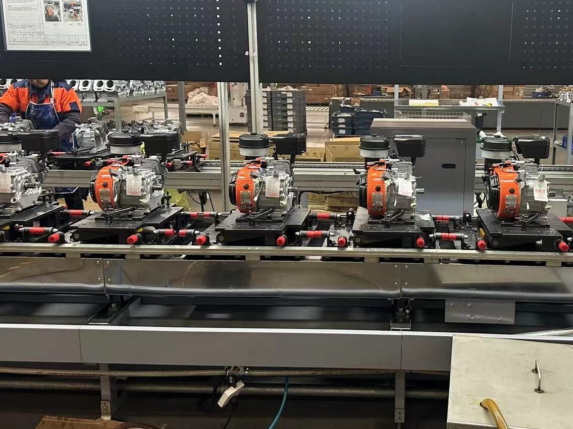
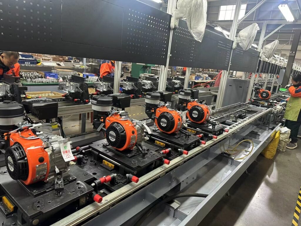
II. Assembly Process of Gasoline Engines for Portable Generators (mass production, assembly line operation, core requirements: coaxiality, tightness, precise clearance)
The assembly of gasoline engines for portable generators is small internal combustion engine assembly line assembly. The cycle time of a single assembly line is 30~60s/unit. It mainly follows the principle of “inside first, outside later; static first, dynamic later; components first, whole machine later; precise clearance; reliable sealing”. All parts must pass incoming inspection (IQC) before assembly, and unqualified parts are strictly prohibited from being put on the line; the assembly process is divided into four stages: parts pre-treatment, core component pre-assembly, whole machine final assembly, initial inspection and fastening. Each stage is equipped with in-process inspection (IPQC) to prevent unqualified products from flowing into the next process.
(I) Preparation Before Assembly: Parts Pre-treatment and IQC Inspection
1. Parts Cleaning: All machined parts (crankshaft, connecting rod, cylinder liner, valve, etc.) must go through ultrasonic cleaning + compressed air blowing to remove machining iron chips, oil stains and cooling liquid. Cleanliness requirements: no visible impurities on the surface, no blockage in the oil channel.
2. Incoming Inspection (IQC) of Parts: 100% full inspection for key dimensions, sampling inspection for non-key dimensions (AQL=0.65). Core inspection items:
– Crankshaft: Roundness and cylindricity of main journal and connecting rod journal ≤ 0.005mm, coaxiality ≤ 0.02mm;
– Cylinder Liner: Inner diameter tolerance ± 0.003mm, roundness ≤ 0.005mm;
– Fitting Clearance between Piston and Cylinder Liner: 0.02~0.04mm (matched by displacement);
– Sealing Surface of Valve and Valve Seat: Contact ring width 1.0~1.5mm, continuous and uninterrupted;
– All Seals (oil seal, gasket, O-ring): No damage, no aging, size matching.
3. Preparation of Tooling and Measuring Tools: The assembly line adopts special tooling fixtures (crankcase positioning fixture, piston connecting rod assembly fixture, timing gear positioning fixture). The measuring tools are digital micrometers, dial indicators, feeler gauges and clearance gauges. All measuring tools are calibrated daily to ensure accuracy.
(II) Core Component Pre-assembly: Assembling Scattered Parts into Components that can be Directly Put on the Line to Improve Final Assembly Efficiency
Pre-assembly is the core link of assembly, accounting for 60% of the total assembly workload. The clearances of all kinematic pairs are adjusted in place during pre-assembly. The core pre-assembled components include piston connecting rod assembly, crankcase assembly, valve train assembly and fuel/ignition system assembly.
1. Pre-assembly of Piston Connecting Rod Assembly
– Step 1: Press the piston pin into the piston pin hole (interference fit, normal temperature press fitting for small engines, hot fitting by heating the piston to 80~100℃ for large engines), install the piston circlip to prevent the piston pin from coming out;
– Step 2: Press the bronze bushing of the connecting rod small end into the connecting rod to ensure the fitting clearance between the bushing and the piston pin is 0.005~0.01mm;
– Step 3: Install the piston rings, use a piston ring installation pliers to avoid breaking the piston rings. The openings of the compression rings and oil rings are staggered by 120°, and the openings are not facing the piston pin and the stressed surface of the cylinder;
– Step 4: Inspection: Use feeler gauge to detect the end gap (0.15~0.30mm) and side gap (0.02~0.05mm) between the piston ring and the cylinder liner. Replace the piston ring if it is unqualified.
2. Pre-assembly of Crankcase Assembly
– Step 1: Press the crankshaft main journal bearing (needle bearing/sliding bearing) into the crankcase bearing seat to ensure the interference fit between the bearing and the seat hole without looseness;
– Step 2: Install the oil pump in the crankcase, test the rotation flexibility of the oil pump without jamming;
– Step 3: Install the crankshaft oil seal, use an oil seal press fitting tool to ensure no deflection during press fitting. Apply grease to the oil seal lip to prevent wear during installation.
3. Pre-assembly of Valve Train Assembly
– Step 1: Press the valve guide and valve seat insert into the cylinder head to ensure interference fit;
– Step 2: Grind the valve and valve seat, use a valve grinding machine. After grinding, perform a sealing test (inject water into the intake/exhaust port of the cylinder head, no leakage for 5min);
– Step 3: Install the valve spring, valve oil seal, rocker arm and push rod on the cylinder head, adjust the clearance between the rocker arm and the valve (cold clearance: intake valve 0.15~0.20mm, exhaust valve 0.20~0.25mm), and detect with a clearance gauge for precise adjustment.
4. Pre-assembly of Fuel/Ignition System Components: Debug the internal of the carburetor (idle speed, main jet position), test the connection between the CDI igniter and the high-voltage coil, adjust the spark plug gap, ensure all wiring terminals are crimped firmly, and perform continuity test.
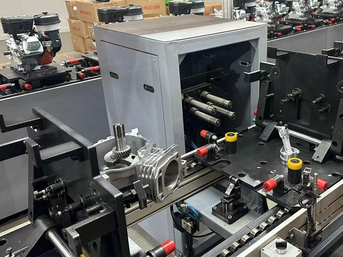
(III) Whole Machine Final Assembly: Core Process of Assembly Line, Assembly in Sequence from Inside to Outside
The final assembly line adopts heavy-duty speed chain or friction roller conveyor line. The number of stations and tooling are configured according to the production capacity. Each station adopts special positioning tooling to prevent wrong or reverse installation of parts. Core processes (in sequence):
1. Crankshaft Installation into Case: Hoist the crankshaft into the crankcase with a special lifting tool to prevent collision of the crankshaft, detect the rotation flexibility of the crankshaft without jamming or abnormal noise;
2. Piston Connecting Rod Assembly Installation into Cylinder: Apply assembly grease (special gasoline engine assembly grease) to the piston connecting rod assembly, press the piston into the cylinder liner with a piston ring compression tool, connect the connecting rod big end with the crankshaft connecting rod journal, tighten the connecting rod bolts (core process of torque control). The tightening torque of the connecting rod bolts is matched by displacement (8~25N·m), using a torque-controlled electric wrench for 100% torque detection to prevent over-tightening or under-tightening;
3. Cylinder Head Assembly: Install the cylinder head (pre-assembled valve train) on the cylinder block, position the cylinder gasket according to the mark (no reverse installation), tighten the cylinder head bolts (cross symmetric tightening), and tighten to the specified torque (15~35N·m) in 2~3 times to ensure the cylinder head is sealed without air leakage or water leakage (no water leakage for air-cooled engines, mainly preventing air leakage);
4. Flywheel Installation: Install the flywheel on the crankshaft output end, position with a positioning pin, tighten the flywheel nut (torque 30~60N·m), detect the flywheel runout (end face circular runout ≤ 0.05mm, radial circular runout ≤ 0.03mm) to ensure stable rotation of the flywheel;
5. Cooling/Lubrication System Assembly: Install the air guide cover, oil filter screen and oil dipstick, add assembly grease, and detect the oil channel patency (compressed air blowing);
6. Fuel/Ignition System Assembly: Install the fuel tank, fuel switch, carburetor, intake pipe, CDI igniter, high-voltage coil and spark plug, connect the fuel pipeline (no leakage) and ignition circuit (no virtual connection), add a rubber gasket at the connection part between the carburetor and the intake pipe, and tighten the clamp;
7. Starting System Assembly: Install the manual recoil starting mechanism (ratchet mechanism unidirectional meshing test). For models with optional electric start, install the starter motor, storage battery and start switch, and connect the power cord;
8. Generator Connecting Flange Assembly: Install the elastic coupling and connecting flange on the crankshaft output end, ensure coaxiality with a positioning pin, tighten the fastening bolts, and detect the runout of the flange end face ≤ 0.05mm;
9. Appearance and Accessory Assembly: Install the muffler, protective cover, handle and nameplate, add a sealing gasket at the muffler connection part to prevent exhaust leakage.
(IV) Initial Inspection and Fastening: Secondary Inspection After Whole Machine Assembly to Eliminate Assembly Errors
1. Bolt Fastening Re-inspection: Use a torque wrench to re-inspect all key bolts (cylinder head bolts, connecting rod bolts, flywheel nuts, flange bolts) 100% to ensure the torque meets the requirements without looseness;
2. Rotation Flexibility Test: Rotate the flywheel by hand, the crankshaft of the gasoline engine rotates smoothly without jamming or abnormal noise, and the number of rotation circles is ≥ 3 (inertial rotation);
3. Sealing Test: Perform air pressure test (0.05MPa) on the fuel pipeline, no leakage for 30s; perform air tightness test (0.03MPa) on the crankcase, no pressure drop for 30s to prevent oil leakage and air leakage;
4. Circuit Detection: Perform continuity test on the ignition system and electric starting system, no short circuit or open circuit, and the spark plug can generate high-voltage spark.
(V) Core Process Requirements of Assembly Process
1. Torque Control: All bolt tightening adopts torque-controlled tools (torque-controlled electric wrench, torque wrench). A torque tracing system is established for key bolts to record the bolt torque value of each product, facilitating quality tracing;
2. Coaxiality Control: The coaxiality error of the crankshaft, flywheel and generator connecting flange is ≤ 0.05mm, positioned by special tooling and detected by dial indicator. Reassemble if unqualified;
3. Clearance Control: The clearances of kinematic pairs such as piston and cylinder liner, valve and rocker arm, crankshaft and bearing are strictly in accordance with the drawing requirements, detected by feeler gauge and clearance gauge 100%;
4. Sealing Control: Special sealant or grease is applied to all sealing surfaces (cylinder gasket, oil seal, gasket, fuel pipeline) without deflection or damage, and 100% of the sealing tests are qualified;
5. Cleanliness Control: It is strictly prohibited to bring iron chips and impurities into the assembly process. The workbench surface is kept clean, and parts are placed in special material boxes to prevent collision and pollution.
III. Testing Process of Gasoline Engines for Portable Generators (divided into single machine test and generator joint commissioning test, core: constant speed performance, reliability, power generation adaptability)
The testing of gasoline engines for portable generators is the last link to ensure product quality. The testing process is divided into single machine performance test (independent test of gasoline engine) and unit joint commissioning test (integral test of gasoline engine + generator). Among them, the single machine test is 100% full inspection, and the unit joint commissioning test is 100% full inspection; after testing, reliability sampling test (bench durability) and final inspection (FQC) are also required. Unqualified products need to be returned to the factory for repair, re-tested after repair, and scrapped if still unqualified.
The core testing standards follow Small Gasoline Engines and Reciprocating Internal Combustion Engine Driven Alternating Current Generators. The testing conditions are mainstream 3000rpm/50Hz or 3600rpm/60Hz (constant speed power generation conditions). The full load is the rated power of the gasoline engine (generally 1.1~1.2 times the rated power of the generator, reserving losses).
(I) Single Machine Performance Test: Independent Bench Test of Gasoline Engine to Detect Basic Performance
Install the gasoline engine on a special test bench, connect with dynamometer (eddy current dynamometer, miniaturized), fuel consumption meter, temperature sensor and speed sensor to independently test the power, fuel consumption, speed, temperature and other indicators of the gasoline engine. Before testing, add qualified gasoline (92#) and special gasoline engine oil (SF/15W-40), start the gasoline engine to preheat for 5min (idle operation), and start testing after preheating. The testing time is 5~10min/unit. Core testing items and standards:
1. Speed Stability Test
– Idle Speed: 1500±100rpm, idle operation for 3min, speed fluctuation rate ≤ ±5%;
– Rated Speed: 3000/3600±50rpm, under no-load/half-load/full-load, speed fluctuation rate ≤ ±2% (core indicator, directly affecting the voltage stability of the generator);
– Speed Response: From idle speed to rated speed, response time ≤ 3s, no speed overshoot or flameout.
2. Power Performance Test
– Rated Power: Actual power ≥ 95% of the rated power (e.g., if the rated power is 3kW, the actual power ≥ 2.85kW);
– Maximum Torque: Actual maximum torque ≥ 90% of the rated torque, torque output is smooth without sudden change;
– Load Characteristic: From 0 load to 100% load, the power rises linearly without speed drop or abnormal noise.
3. Fuel Consumption Rate Test: Under rated conditions, the fuel consumption rate ≤ 380g/(kW·h) (industry standard for small gasoline engines). If the fuel consumption is too high, debug the carburetor (adjust the main jet and idle speed screw).
4. Temperature Test: Operate at full load for 5min, the cylinder head temperature ≤ 250℃, the crankcase temperature ≤ 120℃, the cooling system is normal without overheating.
5. Starting Performance Test: Manual recoil start, start 3 times continuously, start success rate 100%; electric start (optional), start 5 times continuously, start success rate 100%, no jamming of starter motor or tooth striking of flywheel ring gear.
6. Abnormal Noise and Vibration Test: Under rated conditions, the gasoline engine has no obvious abnormal noise (such as cylinder knocking, valve noise, bearing noise), the body vibration acceleration ≤ 5m/s², detected by sound level meter and vibration sensor.
7. Sealing and Leakage Test: During the test, there is no oil leakage, air leakage or exhaust leakage in the fuel pipeline, crankcase, cylinder head, oil seal and other parts. Observe for 5min after shutdown, no dripping.
(II) Unit Joint Commissioning Test: Integral Test of Gasoline Engine + Generator, Core Detection of Power Generation Adaptability
After the single machine test is qualified, assemble the gasoline engine and generator into a complete portable generator, and conduct joint commissioning test on the unit special test bench. The bench is connected with load cabinet (resistance load + inductive load), electrical parameter tester, fuel consumption meter and sound level meter to simulate the actual use scenario and test the matching between the gasoline engine and the generator. The testing time is 10~15min/unit. Core testing items and standards (power generation adaptability is the core):
1. Constant Speed Power Generation Performance Test
– Voltage/Frequency Stability: When the load changes from 0 to 100%, the output voltage fluctuation rate ≤ ±3%, the frequency fluctuation rate ≤ ±1% (e.g., 220V/50Hz, voltage 213.4~226.6V, frequency 49.5~50.5Hz), which mainly depends on the speed stability of the gasoline engine;
– Voltage Recovery Time: From full load to no-load suddenly, the time for the voltage to recover to the rated value ≤ 0.5s, no voltage overshoot, testing the load response capacity of the gasoline engine.
2. Power Matching Test: The rated output power of the unit ≥ 95% of the rated power, the gasoline engine has no overload or speed drop. When working at full load, the speed of the gasoline engine remains 3000/3600rpm without abnormality.
3. Continuous Operation Test: Operate at half load for 10min, the gasoline engine and generator have no overheating or abnormal noise, the electrical parameters are stable, and the fuel consumption rate meets the rated value of the whole machine.
4. Idle Charging Test (for units with electric start): When idling, the charging winding of the generator outputs 13.5~14.5V voltage, which can charge the storage battery normally, and the charging current ≥ 0.5A.
(III) Reliability Sampling Test: Bench Durability Test to Verify Long-term Use Reliability
Both single machine test and unit joint commissioning test are 100% full inspection. The reliability test is a sampling test with a sampling ratio of 1~2 units per batch (batch quantity ≤ 500 units). The bench durability test is adopted to simulate the actual use scenario. The test time is divided into short-term durability (200h) and long-term durability (500h). Core test content:
1. Working Condition Setting: Operate according to the cycle condition of “idle speed 10% + half load 40% + full load 50%”, shut down for inspection every 2h, and record indicators such as speed, power, fuel consumption, temperature and electrical parameters;
2. Detection Items: No failure, no oil leakage and no abnormal noise during operation. After the durability test, disassemble the gasoline engine and check the wear of key parts:
– Cylinder Liner Wear ≤ 0.01mm/100h;
– Piston Ring Wear ≤ 0.02mm/100h;
– Crankshaft Main Journal and Connecting Rod Journal Wear ≤ 0.005mm/100h;
– The sealing surface of the valve and valve seat has no obvious wear, and the sealing performance is qualified;
3. Qualification Standard: After the durability test, the power of the gasoline engine decreases ≤ 5%, the fuel consumption rate increases ≤ 10%, the power generation performance of the unit still meets the standard, and there is no permanent failure.
(IV) Environmental Protection and Comfort Test: Emission, Noise and Vibration (mandatory national standard requirements)
1. Emission Test: Follow Limits and Measurement Methods for Exhaust Pollutants from Motorcycles (China Stage VI) (referenced by small gasoline engines), test the emissions of CO, HC, NOx and other pollutants, and the emission value ≤ national standard limit. Carburetor models meet the standard by adjusting the air-fuel ratio and installing small three-way catalytic converters, and EFI models meet the standard by precisely controlling the air-fuel ratio through ECU;
2. Noise Test: Follow Reciprocating Internal Combustion Engine Driven Alternating Current Generators, the noise ≤ 75dB(A) under rated conditions at a distance of 1m from the unit (national standard for portable generators), mainly reducing noise through muffler, air guide cover and rubber shock absorber;
3. Vibration Test: The overall vibration acceleration of the unit ≤ 3m/s², absorbing vibration through the elastic coupling between the gasoline engine and the generator, and the rubber shock absorber between the unit and the case.
(V) Final Inspection (FQC) and Packaging: Final Inspection to Ensure Factory Quality
1. Final Inspection: For all units that pass the test, conduct final inspection of appearance, performance and accessories. Inspection items: no collision or scratch on the appearance, complete nameplate information, qualified starting performance, normal idle/rated speed operation, and complete accessories (recoil rope, oil dipstick, instruction manual, warranty card);
2. Shutdown and Protection: Drain the gasoline and engine oil in the gasoline engine (prevent deterioration during long-term storage), apply anti-rust oil on the cylinder wall, piston ring and other parts, seal the fuel tank and oil port to prevent dust and water entry;
3. Packaging: Adopt carton + foam packaging to fix the unit and prevent collision during transportation. The packaging is marked with product model, rated power, speed, weight, warning signs and other information.
(VI) Handling of Unqualified Products
Unqualified products found during the test are divided into minor unqualified (such as appearance scratches, slightly excessive speed fluctuation rate) and serious unqualified (such as insufficient power, oil leakage, unstable power generation voltage, abnormal noise):
1. Minor Unqualified: Re-test after repair, and leave the factory only if qualified;
2. Serious Unqualified: Return to the factory for disassembly, analyze the cause of unqualified, replace relevant parts, re-assemble and test, and scrap if still unqualified;
3. Quality Tracing: Establish a quality tracing file for unqualified products, record the cause of unqualified, handling method and responsible person. For batch problems, timely optimize the assembly process or parts procurement standards.
IV. Core Summary
The structure, assembly and testing process of gasoline engines for portable generators all focus on three core needs: “portability, constant speed power generation and reliability”. Compared with automotive and engineering machinery gasoline engines, their structure is extremely lightweight and integrated, removing complex electronic control and auxiliary systems, mainly OHV air-cooled single-cylinder four-stroke; the assembly process emphasizes torque control, coaxiality control, precise clearance and sealing, adopting assembly line operation with strict inspection in each process; the testing process is divided into single machine and unit joint commissioning, 100% full inspection of basic performance, sampling inspection of reliability, focusing on speed stability (directly affecting power generation quality) and long-term use reliability (adapting to the field and emergency use needs of portable scenarios).
The core logic of its overall process is: simplify the structure to adapt to portability, precise assembly to ensure performance, and strict testing to improve reliability, ultimately achieving perfect matching between the gasoline engine and the generator, and ensuring the stable and safe operation of the portable generator in emergency, field, outdoor operation and other scenarios.