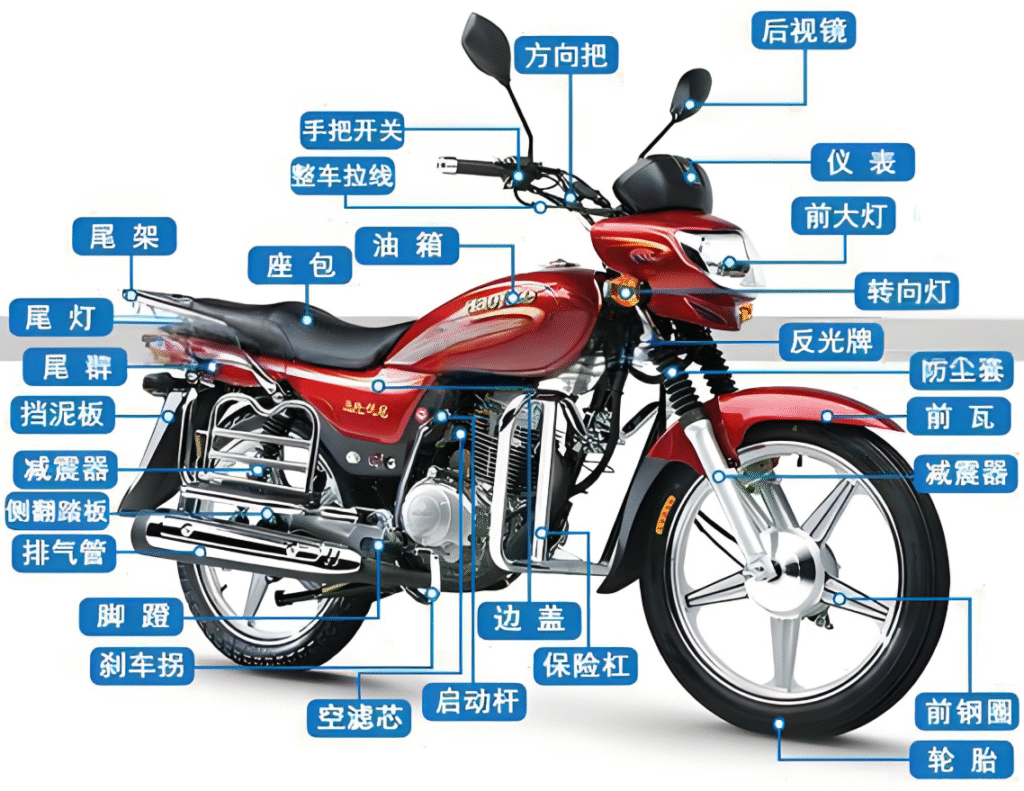
Simple Reference Process for Fuel-Powered Motorcycle Assembly Line
Motorcycle Final Assembly – Detailed Standard Operating Procedure (SOP)
Scope: ≤250 cc two-wheel street/dirt motorcycles, 90 s takt, 120 k units/year two-shift

- Purpose
Provide step-by-step, torque-controlled and test-verified instructions to guarantee consistent quality, safety and traceability.
- Process Overview
- Detailed Operations (Station-Step-Action-Torque-QC)
Station #10 – Frame Loading
1.1 Action: Lift frame onto pallet with electric hoist, align locating pins.
1.2 Scan VIN and verify engraving depth ≥0.2 mm, no broken strokes.
Station #20 – Engine Pre-assembly
2.1 Lift engine with dual-sling hoist, place on frame mounts.
2.2 Hand-start two M10×120 flange bolts → power tool pre-torque → final torque 25 N·m ±2 N·m.
2.3 Red torque-mark paint; check no axial play.
Station #30 – Swing-arm & Chain
3.1 Press needle bearings into swing-arm with 5 t press (≤5 kN force).
3.2 Install sprocket: M10×1.25 bolts, Loctite 243 → cross-pattern 49 N·m → punch-lock.
3.3 Insert Φ20 swing-arm shaft → M20×1.5 nut → torque 80–90 N·m → yellow torque-mark.
Station #40 – Rear Shock
4.1 Upper eye bolt M10×70 + self-locking nut 30–40 N·m.
4.2 Lower bolt M10×60 30–40 N·m; verify no side twist.
Station #50 – Front End
5.1 Press bearings & seals into upper triple clamp (depth 10.5 mm).
5.2 Fork tubes into triple clamp:
• Upper pinch bolts M8×35 17–22 N·m
• Lower pinch bolts M8×45 10–12 N·m
5.3 Front wheel:
• Fit tire, inflate to 220 kPa ±10 kPa
• Mount disc rotor, M8×25 bolts 25–30 N·m cross-pattern
• Speed sensor 5 N·m.
Station #60 – Handlebar & Steering Stem
6.1 Stem nut 40 N·m ±2 N·m (green mark).
6.2 Handlebar center 380 mm ±5 mm from seat tip; clamp nuts 35–40 N·m.
Station #70 – Fuel System
7.1 Tank leak test: 30 kPa air, 30 s submerged, zero bubbles.
7.2 Mount tank: two M8×45 bolts 20–25 N·m with rubber cushions.
7.3 Connect Φ7.5 fuel hose → double ear clamps → pull-off ≥150 N.
Station #80 – Wiring & Electrics
8.1 Route main harness per left/right/earth/coil sequence, tie-wraps every 150–180 mm.
8.2 Battery: 12 V 9 Ah Li-ion, M6×16 bolts 6–8 N·m; open-circuit ≥12.8 V.
8.3 Key-on self-check: lights, horn, tachometer, fuel pump, idle valve → PASS sticker.
Station #90 – Plastics & Seat
9.1 Front side cowls: self-tapping screws + flat washer 3–4 N·m diagonal pattern.
9.2 Tail & seat: seat latch engagement ≤1.5 mm gap; tail M6 nuts 6–8 N·m.
Station #100 – Functional Test
10.1 Brake force: front ≥0.6 kN, rear ≥0.5 kN, side-to-side ≤0.1 kN.
10.2 Lighting: high beam ≥15 000 cd, position lamp 5 W ±0.5 W.
10.3 Idle emission: CO ≤3.5 %, HC ≤1 500 ppm.
Station #110 – Road Test & Final QC
11.1 Road run: 40 km/h coast ≥200 m; braking ≤7 m from 30 km/h.
11.2 Final check: zero cosmetic defects, 100 % torque marks visible, 10 % random re-torque audit.
- Critical Torque List (excerpt)
| No. | Joint | Thread | Torque (N·m) | Tool | Color |
|---|---|---|---|---|---|
| 1 | Engine-frame bolts | M10×120 | 25 ±2 | ½” torque wrench | Red |
| 2 | Swing-arm nut | M20×1.5 | 85 ±5 | ¾” torque wrench | Yellow |
| 3 | Rear sprocket bolts | M10×1.25 | 54 ±5 | ½” torque wrench | Blue |
| 4 | Steering stem nut | M25×1.5 | 40 ±2 | ½” torque wrench | Green |
| 5 | Fork upper pinch | M8×35 | 20 ±3 | ¼” torque driver | White |
| 6 | Handlebar clamp | M8×45 | 38 ±2 | ¼” torque wrench | Green |
| 7 | Tank bolts | M8×45 | 22 ±2 | ¼” gun + wrench | Yellow |
| 8 | Battery clamp | M6×16 | 7 ±1 | ¼” gun | — |
- Shop-Floor Document Package (print-ready)
- Job Instruction Sheet – A3 color, exploded view + torque + key points per station
- Torque Checklist – 38 critical joints, shift-by-shift log
- QC Record Sheet – 28 inspection items, barcode entry to MES
- Defect & Countermeasure Card – 15 top issues with immediate fixes
