Pneumatic Transfer Lifting / Elevating Platform for Assembly Line
Pneumatic Transfer Lifting Table for Upper and Lower Layer Conveying in Assembly Lines: Structure, Working Principle and Application
The pneumatic transfer lifting table is a core non-standard automated auxiliary component for the connection of upper and lower layers of assembly/conveying lines. It relies on pneumatic power to achieve vertical lifting of the worktable surface, and cooperates with a belt/roller conveying mechanism to complete the seamless transfer of workpieces between upper and lower conveying lines. Featuring fast response, stable load capacity and strong adaptability, it is widely used in the process connection of multi-layer speed chain lines and belt conveying lines, and is a key device for realizing the three-dimensional layout of assembly lines and saving floor space.
This equipment is characterized by the integration of “lifting + conveying”. The lifting action meets the height matching of upper and lower layers, and the conveying action realizes unpowered/powered connection between workpieces and upstream and downstream line bodies. The whole process can be linked with the production line PLC to achieve automatic circulation, adapting to the batch and continuous production requirements of industrial assembly lines.
I. Core Overall Structure
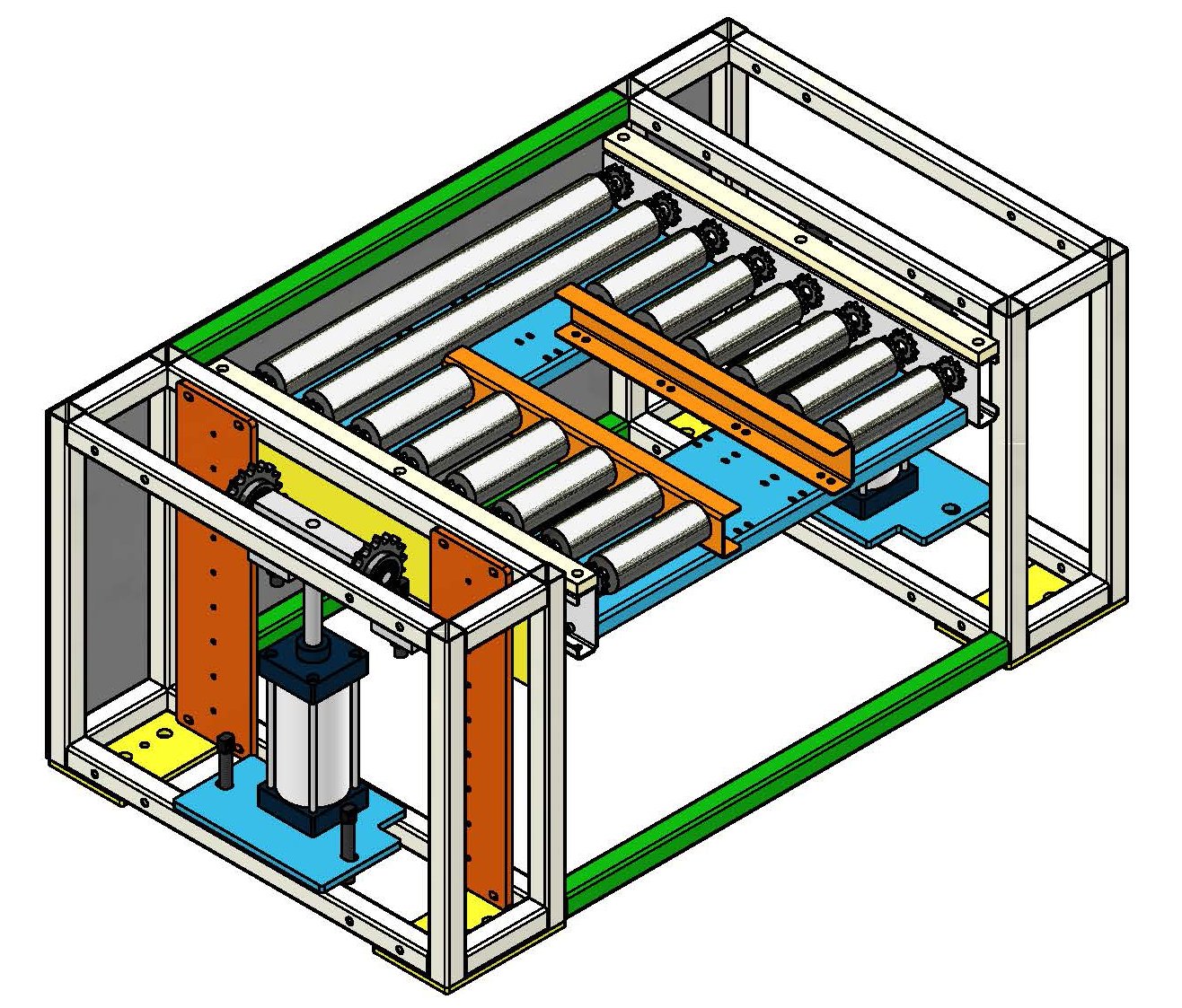
The pneumatic transfer lifting table adopts a modular combined structure, with all components integrated in a steel frame. It is divided into six core parts by function: basic support frame, lifting drive system, table conveying system, guiding and positioning system, pneumatic control system and auxiliary protection system. All components cooperate to achieve “accurate lifting positioning and stable conveying connection”. The detailed structural disassembly is as follows:
1. Basic Support Frame
- The main body is a section steel welded/bolt-spliced structure (square steel, channel steel and I-steel are commonly used), customized according to load and table size, serving as the load-bearing foundation of the entire equipment;
- The bottom is equipped with leveling feet/universal wheels (with brakes) for easy equipment installation, leveling and production line layout adjustment;
- The frame reserves space for pneumatic pipelines and electrical wiring inside, and is spray-painted for rust prevention outside, adapting to the industrial workshop environment.
2. Lifting Drive System (Core Power Component)
As the core executive unit of pneumatic drive, it determines the lifting load and lifting speed, consisting of the following components:
- Pneumatic cylinder: The mainstream type is double-shaft double-outlet cylinder/piston type lifting cylinder (multi-cylinder parallel connection for heavy load scenarios), installed vertically inside the frame. The cylinder block is fixed on the base, and the piston rod is connected to the conveying table, serving as the direct power source for lifting;
- Air source treatment assembly: Including filter, pressure reducing valve and oil mist separator (triple unit), it filters impurities in compressed air, adjusts air pressure (the general working air pressure is 0.4-0.6MPa), and lubricates the inside of the cylinder to avoid cylinder jamming;
- Connection transmission parts: The piston rod and the table are connected through floating joints and connecting brackets to offset installation errors, ensure the table level during lifting, and avoid jamming.
3. Table Conveying System (Core Connection Component)
It realizes the conveying and transfer of workpieces between the lifting table and upstream and downstream line bodies, matching the main conveying form of the assembly line. The mainstream type is belt conveying (suitable for light and medium workpieces, meeting the demand of “belt conveying”), and the roller conveying type can be replaced for some heavy load scenarios. The core components are:
- Conveying belt: PVC/PU industrial belts are commonly used (wear-resistant and anti-static, suitable for industrial workpieces), with the belt width and table length customized according to the workpiece size;
- Drive unit: A small geared motor plus a driving roller, with a driven roller matched with a tensioning mechanism to realize uniform speed conveying of the belt. The conveying speed can be matched with the main production line (generally 0.5-2m/min);
- Table frame: Made of aluminum alloy profiles/thin steel plates, it bears the conveying mechanism and is rigidly connected with the piston rod of the lifting cylinder to ensure the stability of the conveying system during lifting.
4. Guiding and Positioning System (Ensuring Lifting Precision)
It avoids table offset and inclination during lifting, and ensures accurate positioning (positioning accuracy ±0.5mm) between the table and the upper and lower conveying lines. The core components are:
- Linear guiding mechanism: The mainstream type is linear guide rail + slider (installed symmetrically on both sides). The guide rail is fixed on the support frame, and the slider is connected to the conveying table, restricting the table to only perform vertical movement;
- Positioning and limiting parts: Including upper limit sensor, lower limit sensor and mechanical anti-collision block. The upper limit realizes accurate docking with the upper line body, the lower limit realizes accurate docking with the lower line body, and the mechanical anti-collision block provides double protection to avoid cylinder damage caused by over-travel;
- Table level adjustment parts: Fine-tuning gaskets are equipped between the slider and the table, which can calibrate the table level during installation to prevent workpiece side slip during conveying.
5. Pneumatic Control System (Realizing Action Control)
It controls the lifting action of the cylinder, supports manual/auto mode, and links with the production line. The core components are:
- Solenoid directional valve: The mainstream type is a 5/2-way solenoid valve, which controls the flow direction of compressed air through electrical signals to realize the extension (lifting) and retraction (lowering) of the cylinder;
- Throttle valve: Installed at the air inlet/outlet of the cylinder, it adjusts the flow of compressed air to realize stepless speed regulation of lifting speed (the lifting speed is slightly faster, and the lowering speed is gentle to avoid workpiece impact);
- Pressure switch/magnetic switch: The magnetic switch is installed on the cylinder to detect the extension/retraction position of the piston rod, feed back the signal to the PLC, and realize the interlock control of actions; the pressure switch monitors the air source pressure and alarms when the pressure is insufficient to avoid equipment failure.
6. Auxiliary Protection System (Industrial Safety Adaptation)
It adapts to the workshop production safety specifications and prevents accidental contact by personnel or workpiece falling during equipment operation:
- Safety guard edges/baffles: Aluminum alloy guard edges are installed around the conveying table to prevent workpiece side slip and falling during lifting/conveying;
- Emergency stop button: An emergency stop switch is installed on the side of the equipment to cut off the air source and power supply with one key and stop all actions in an emergency;
- Anti-pinch gap design: The moving areas of the guiding mechanism and cylinder are closed/protected with gaps to prevent personnel’s fingers and tools from entering by mistake;
- Grounding for anti-static: The table and frame are grounded to adapt to the conveying of electronic components and precision parts.
II. Working Principle
The core principle of the pneumatic transfer lifting table is “linear reciprocating motion of pneumatic power + precise lifting of mechanical guidance + workpiece transfer of belt conveying”. The whole process can be divided into four stages: standby positioning, lifting/lowering connection, conveying transfer and reset standby, supporting manual single-point control and automatic control linked with production line PLC (the mainstream industrial application is auto mode). The following is the standard automatic working process for the connection of upper and lower layer belt conveying lines (taking the workpiece transfer from the lower layer line to the upper layer line as an example):
- Standby positioning: The initial state of the equipment is standby at the lower limit. The conveying table is at the same horizontal height as the table of the lower layer belt conveying line. The air source triple unit maintains the working air pressure of 0.4-0.6MPa, the solenoid valve is in the power-off reset state, and the cylinder piston rod is retracted;
- Signal trigger: The workpiece on the lower layer line is conveyed to the table position of the lifting table. The photoelectric sensor of the line detects the workpiece in place, sends the signal to the production line PLC, and the PLC sends a lifting command to the lifting table;
- Precise lifting: The 5/2-way solenoid valve of the lifting table is energized for commutation, compressed air enters the rodless cavity of the cylinder, and pushes the piston rod to extend, driving the conveying table to lift vertically along the linear guide rail; when the cylinder piston rod reaches the upper limit, the magnetic switch on the cylinder detects the signal and feeds it back to the PLC, the PLC sends a stop command, the solenoid valve is powered off, the table is locked at the horizontal height of the upper layer line, with positioning accuracy ±0.5mm, completing the lifting positioning;
- Conveying transfer: After the table is accurately docked with the upper layer belt conveying line, the PLC sends a start command to the conveying motor of the lifting table, the table belt starts to run (the speed is consistent with the upper layer line), and conveys the workpiece from the lifting table to the upper layer line;
- Reset standby: After the workpiece completely leaves the lifting table, the photoelectric sensor of the upper layer line detects the workpiece in place, feeds the signal back to the PLC, and the PLC sends a lowering command to the lifting table; the solenoid valve is energized for commutation again, compressed air enters the rod cavity of the cylinder, pulls the piston rod to retract, drives the table to drop vertically along the guide rail to the lower limit. After the magnetic switch feeds back the signal, the table stops, the conveying motor is powered off, and the equipment returns to the initial standby state, waiting for the next workpiece signal.
The process of workpiece transfer from the upper layer to the lower layer is the reverse of the above. The core is to realize cylinder lifting through solenoid valve commutation, and realize interlock and precise control of actions through sensors, with no manual intervention throughout the process, adapting to the continuous production of the assembly line.
Supplementary note: The throttle speed regulation principle of the pneumatic system — the intake throttle valve controls the lifting speed, and the exhaust throttle valve controls the lowering speed. By adjusting the throttle valve opening, the flow of compressed air is changed, so as to realize the precise regulation of the lifting speed and avoid workpiece impact and side slip caused by too fast lifting speed.
III. Core Uses and Application Scenarios
As a core connection device for the three-dimensional layout of assembly/conveying lines, the pneumatic transfer lifting table is mainly used to realize the seamless and automatic transfer of workpieces between upper and lower layer conveying lines. It replaces manual handling, improves the automation level of the production line, saves floor space, and can also cooperate with the process layout of the production line to realize functions such as “upper and lower layer process connection, workpiece buffering and cross-layer conveying”. It is widely used in assembly lines of auto parts, 3C electronics, home appliances, medical devices and other industries. The specific application scenarios and supporting characteristics are as follows:
1. Cross-layer Conveying of Workpieces in Multi-layer Assembly Lines (Core Use)
This is the most mainstream application scenario, suitable for the three-dimensional layout of double-layer/three-layer speed chain assembly lines and belt conveying lines, solving the problem of insufficient floor space of single-layer production lines:
- Example: In an auto parts assembly line, the lower layer line realizes workpiece feeding and initial processing, the workpiece is transferred to the upper layer line through a pneumatic transfer lifting table for finish processing and assembly, and after the completion of the upper layer line, the workpiece is transferred back to the lower layer line through the lifting table for blanking, realizing “linkage of upper and lower layer processes and more than 50% improvement in production line space utilization”;
- Supporting characteristics: Seamless linkage with the main production line PLC, the lifting and conveying actions are synchronized with the main production line, supporting continuous transfer of batch workpieces, and adapting to a load range of 5-500kg (customized according to cylinder specifications).
2. Process Connection and Station Docking of Assembly Lines
In the cross-process and cross-station scenarios of assembly lines, if there is a height difference between upstream and downstream stations (such as upper and lower layer detection stations and assembly stations), the pneumatic transfer lifting table can be used to realize height adaptation and conveying transfer of workpieces:
- Example: In a 3C electronic assembly line, the lower layer is a circuit board plug-in station, and the upper layer is a circuit board detection station. The circuit board after plug-in is transferred to the upper layer detection station through the lifting table, and transferred back to the lower layer for continuous assembly after detection, realizing seamless connection between stations and avoiding low efficiency and workpiece damage caused by manual handling;
- Supporting characteristics: The table can be customized with an anti-static design to adapt to the conveying of precision electronic components, and the lifting positioning accuracy is high to ensure the precise positioning of workpieces at detection/assembly stations.
3. Workpiece Buffering and Temporary Storage of Production Lines
When a certain process of the assembly line is shut down for a short time (such as detection equipment failure and slow manual assembly), the pneumatic transfer lifting table can be used as a temporary buffer table to realize temporary storage of workpieces and avoid main production line blockage:
- Example: In a home appliance assembly line, if the screw locking station of the upper layer line is shut down for a short time, the workpieces of the lower layer line can be lifted by the lifting table and temporarily stored on the table. After the locking station is restored, the buffered workpieces are conveyed to the upper layer line through the lifting table to ensure the continuous operation of the main production line;
- Supporting characteristics: The table length can be customized to increase the buffer capacity, supporting sequential buffering and one-by-one conveying of multiple workpieces, and equipped with workpiece in-place detection sensors to avoid buffer overflow.
4. Feeding/Blanking Connection of Automated Production Lines
At the feeding end and blanking end of the assembly line, if there is a height difference between the raw material/finished product storage rack and the production line, the pneumatic transfer lifting table can be used to realize feeding transfer of raw materials and blanking transfer of finished products, and cooperate with manipulators and AGVs to realize fully automatic feeding and blanking:
- Example: In a home appliance shell assembly line, the lower layer AGV conveys the raw material shell to the lifting table, the lifting table rises to the same height as the upper layer assembly line and conveys the shell to the assembly line; the finished product after assembly is lowered to the lower layer through the lifting table and conveyed to the finished product warehouse by AGV, realizing the fully automatic circulation of “AGV + lifting table + assembly line”;
- Supporting characteristics: It can be equipped with an AGV docking positioning mechanism to ensure accurate docking between AGV and the lifting table, and support signal linkage with manipulators and AGVs to realize unmanned production.
5. Customized Process Adaptation of Non-standard Production Lines
For non-standard production lines with special-shaped workpieces and special assembly processes, the table size, load, lifting height and conveying form of the lifting table can be customized to realize adaptive connection:
- Example: In a heavy auto parts assembly line, a heavy load pneumatic lifting table with multi-cylinder parallel connection (load over 500kg) is customized, matching with a roller conveying table to realize the cross-layer transfer of heavy parts;
- Example: In a small precision part assembly line, a lifting table with a micro belt conveying table is customized to adapt to the conveying of small-sized parts, equipped with anti-falling guard edges to ensure the safety of part conveying.
IV. Core Differences from Other Lifting Connection Equipment
Other commonly used lifting connection equipment in assembly lines include electric lifting tables and hydraulic lifting tables. Relying on its own characteristics, the pneumatic transfer lifting table has become the first choice for scenarios with light and medium load, high-frequency connection and no oil pollution requirements in workshops. The core differences are as follows:
| Equipment Type | Power Source | Load Range | Lifting Speed | Workshop Adaptability | Maintenance Difficulty | Applicable Scenarios |
|---|---|---|---|---|---|---|
| Pneumatic transfer lifting table | Compressed air | 5-500kg | Fast (50-200mm/s) | Oil-free, explosion-proof requirements | Low (only air source maintenance) | Light & medium load, high-frequency connection |
| Electric transfer lifting table | Motor + lead screw | 5-1000kg | Slow (20-80mm/s) | No special requirements | Medium (lead screw and motor maintenance required) | Heavy load, high-precision positioning |
| Hydraulic transfer lifting table | Hydraulic oil | 500-5000kg | Medium (30-100mm/s) | Oil pollution allowed | High (hydraulic oil and oil pump maintenance required) | Ultra-heavy load, low-speed connection |