Custom Guide for HMI and PLC Control Systems in Assembly Lines
This guide shows how to tailor an HMI–PLC system for logistics assembly lines without discussing cycle time. First, capture real user stories: operators want one-tap clarity, maintenance needs fault location in <3 min, logistics staff require live pallet tracking. Translate these into hardware—CPU with 30 % spare, remote I/O and valve terminals on one Profinet cable—and software—state-machine FB per station, JSON recipes, dual-level HMI: 7″ station panels for animations plus a 15″ line PC map. Build maintainability inside: self-diagnostic struct array, tool-free M12 swaps, Git-style version tags, role-based RFID login. Follow a four-week rollout: survey, POC, integrate vision/RFID, pilot. Result: a hot-swappable, self-documenting line that users can maintain in minutes, not hours.
Custom-Built HMI & PLC Control for Assembly Lines – A Practical Guide
(For Intra-Logistics Assembly Lines, Cycle-Time Discussion Excluded)
- Requirement Layer – What a logistics-type assembly line really needs
1.1 Scope
- Handle “material flow + simple assembly actions” only; no deep process recipes (e.g. torque curves).
- Typical stations: load → scan & bind → assemble (press, clip, screw) → vision check → label → unload buffer.
1.2 User personas
- Operator: high-school level, two-shift, gloves on, wants “one-glance, one-tap”.
- Maintenance tech: electrician background, must locate a broken sensor or valve in ≤ 3 min.
- Logistics team-lead: needs to know “where is the pallet now, any jam?” and re-route on the fly.
1.3 Pain points collected on the shop-floor
- Brown-field upgrade: legacy PLC code locked; mixed HMI brands, seven field-bus dialects.
- Downtime detective work: alarm only says “Station 3 Error”; tech ends up on the floor with a meter.
- Product change-over: 20 min of laptop-in-the-aisle to swap recipes.
- Function Layer – Turn needs into plug-and-play modules
2.1 Hardware backbone – “PLC + remote I/O + valve-terminal” on one network
- CPU ≥ 1 MB program memory, ≥ 1 ms/1 k instructions, 30 % spare; two independent Ethernet ports (HMI / vision).
- Remote I/O: Profinet/EtherNet-IP slices mounted on station posts – saves 30 % tray-runs.
- Valve terminal on the same bus, short-circuit isolated; single coil hot-swap without stopping neighbours.
2.2 HMI architecture – “station-level embedded panel + line-level industrial box-PC”
- Station: 7” flush capacitive, ≥ 800 × 480, IP65, glove-friendly; use vendor-small HMI (Siemens KTP, Kinco GL070E).
– Top 15 % static: work-order ID, part number, OK / NOK counters.
– Middle 60 % dynamic: assembly animation, current step highlighted, next-step preview.
– Bottom 25 % manual bar: jog forward / backward, gripper open/close, E-stop. - Line: 15” box-PC, fan-less, running open-source SCADA (Node-RED + InfluxDB) for “logistics map”: live pallet positions, jam heat-map, historical trace.
2.3 Control logic – “state-machine + recipe” dual engine
- One IEC function-block per station, written in SCL: IDLE → LOAD → ASSEMBLE → CHECK → RELEASE → IDLE.
- Recipe stored as JSON string in PLC data block: ProductID, StationEnableMask, TorqueValue, VisionProgramNo…
HMI writes whole JSON via drop-down or file import – no program download needed.
2.4 Key functions
- Traceability: pallet RFID linked to work-order; PLC updates EPC every 200 ms; HMI “pallet CV” button shows last 20 stations in < 3 s.
- Vision integration: camera OK/NG result mapped to ModbusTCP registers 0x0001-0x0010; HMI alarm page auto-saves snapshot to \SD\VisionSnap.
- Remote support: line-PC runs OpenVPN client; vendor can view variable table read-only, cannot change code.
- Maintainability Layer – Designed-in, not retro-fitted
3.1 Self-diagnostics database
- At start-up PLC scans all I/O slices, valve terminals, drives; fills struct array Diag[1..32] with ModuleID, Status, ErrorCode, TimeStamp.
- Maintenance HMI page lists everything: red = fault; click shows “likely cause + spare part number + drawing page”.
3.2 Tool-free replacement
- Sensors / valves use M12 quick-connect with keying; HMI offers “force / mask” button – tech masks point, swaps hardware, unmasks – line never stops.
3.3 Version control
- PLC program stores Git-style tag (ProgramVersion, CommitHash); visible in HMI “About”.
After any field change tech copies .ap13 to USB; inserting USB into line-PC auto-archives to \NAS\FWBackup.
3.4 Role-based access
- Operator: reset & counter clear only.
- Maintenance: force I/O, mask station.
- Process engineer: edit recipe, download firmware.
All via RFID badge + PLC user-management; HMI just shows “badge login” button.
- Quick-selection cheat-sheet
| Level | Part | Key specs | Notes |
|---|---|---|---|
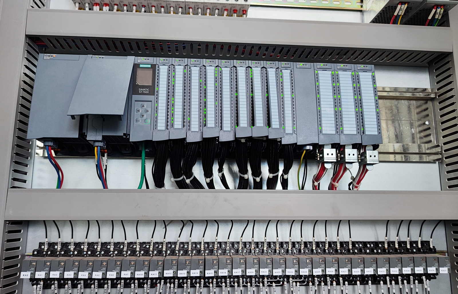
| PLC | Siemens S7-1500 1511TF-1 PN | 1 MB work memory, ≥128 DI/DO, 2×PN | Motion + remote I/O in one |
| Remote I/O | ET200SP IM155-6 PN HF | 64 modules / rack, hot-swap | BaseUnit separable, no re-wiring |
| Valve terminal | Festo VTUG Profinet | 24 VDC, 24 positions, short-circuit proof | Same bus as I/O |
| Station HMI | GL070E | 7” capacitive, A9 CPU, 512 MB Flash | Free EV5000, reusable templates |
| Line PC | ITA-1010 | Celeron J1900, 4 GB + 64 GB SSD | 15” resistive, Node-RED ready |
| Remote | 5G CPE Pro 2 | Campus 5G SIM | VPN dial-in from SCADA |
- Four-week roll-out template
Week 1: on-site survey → I/O count → network drawing → panel layout
Week 2: hardware arrival → POC code (dry-run state machine) → HMI templates → user review
Week 3: final code + recipe → vision/RFID hook-up → diagnostics DB → maintenance training
Week 4: 3-day 2-shift pilot → punch-list close → FAT sign-off → go-live
One-sentence takeaway
Treat the logistics assembly line like hot-swappable Lego: PLC is the base-plate, HMI the instruction sheet, diagnostics the part-number list. Design the three layers once and anyone can swap a module in 10 minutes – no vendor required.