| 01 | Incoming QC | Check BOM, verify enclosure, power modules, PCBs, harnesses, fasteners & insulators for damage and correct part numbers. | Lot numbers, certificates, ESD-sensitive parts | Calipers, multimeter |
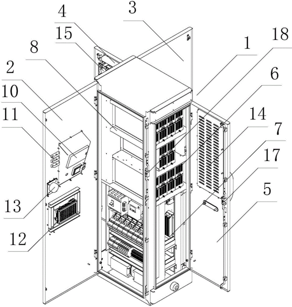
| 02 | Cabinet Pre-assembly | Install grounding busbar, cable glands, fan brackets; pre-fit door locks & hinges. | Ground resistance ≤ 0.1 Ω, threads without burrs | Electric screwdriver, torque wrench (8 Nm) |
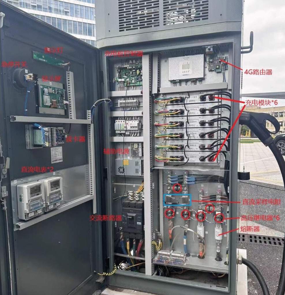
| 03 | Power-Module Installation | Slide modules into rails, tighten 4×M6 bolts, connect DC busbars & AC input copper bars. | Module sequence matches label, anti-misinsertion | Socket wrench, insulated gloves |
| 04 | Control Unit Assembly | Mount main board, billing board, display & indicator lights; connect flat cables (check keying). | No cable compression, latches fully engaged | ESD wrist strap, Phillips screwdriver |
| 05 | Harness Routing | Route per wiring diagram: AC input, DC output & comm. lines in separate ducts; zip-tie spacing 150 mm. | HV/LV separation, slack ≤ 30 mm | Cable-tie gun, wire label printer |
| 06 | Insulation & Hi-Pot Test | AC circuit: 1 500 V AC / 1 min, no breakdown; DC circuit: 1 000 V DC / 1 min, leakage ≤ 10 mA. | Disconnect SPD before test | Hipot tester |
| 07 | Functional Commissioning | Power-on self-test: communication, card reader, billing, insulation monitor, fan control, E-stop. | Record & clear fault codes | DC load, BMS simulator |
| 08 | Burn-in Test | Full-load run 2 h; temperature rise ≤ 65 K, no abnormal noise or alarms. | Log temp, current & voltage every hour | Burn-in rack, IR thermometer |
| 09 | Cleaning & Final QC | Remove label residue & fingerprints, verify silkscreen, apply warning labels (“High Voltage”, “Operating Guide”). | No scratches, labels bubble-free | IPA, lint-free cloth |
| 10 | Packing & Warehousing | Seal in anti-moisture bag, place in honeycomb carton, four-corner foam, “#” strapping. | Accessories: manual, CoC, keys | Strapping machine, digital scale |


