
Principle of Friction Wheel Conveyance & Force Calculation
Friction Wheel Force Calculator
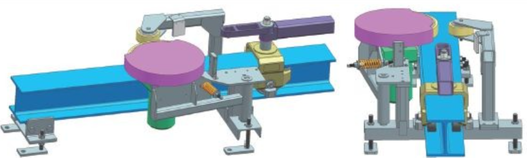
I. Core Structure & Working Principle
Friction Drive System (FDS) uses distributed friction drive stations along the track. The high-friction wheel clamps the trolley beam and drives the trolley forward by static friction.
1. Main Components
- Track System (straight, curved, turnout)
- Friction Drive Station (motor, PU friction wheel, spring clamp, sensor)
- Load Trolley / Spreader
- PLC Control & Precision Positioning
2. Working Principle
- Spring/cylinder provides clamping force FN
- Motor drives friction wheel, static friction pulls the trolley
- Distributed relay drive (3–8m per station)
- Controlled slip for overload protection
II. Friction Force & Clamping Force Calculation
1. Traction Force (Required Driving Force)
Ftraction ≈ f × G
- f = rolling friction coefficient (0.01–0.03)
- G = total weight (N)
2. Friction Force (Driving Force)
Ffriction = μ × FN
- μ = friction coefficient (0.5–0.8 for PU‑Steel)
- FN = spring clamping force
3. Minimum Clamping Force
FN ≥ (K × f × G) / μ
Engineering rule: Clamping force ≈ 7.5% of total weight
4. Spring Stiffness Calculation
FN = k × x
- k = spring stiffness (N/mm)
- x = spring compression (mm)
III. Quick Reference Table
| Total Mass (kg) | Traction Force (N) | Recommended Clamping Force (N) |
|---|---|---|
| 500 | ~100 | 300–400 |
| 1000 | ~200 | 600–800 |
| 2000 | ~400 | 1200–1600 |
| 3000 | ~600 | 1800–2400 |
IV. Core Summary
- Drive mode: distributed friction relay drive
- Key force: static friction = μ × clamping force
- Engineering design: clamping force ≈ 7.5% of total weight
- Features: energy saving, low noise, high precision, easy maintenance