Structure and Manufacturing Process of Electric Scooter Hub Motors
The hub motor for scooters features a outer rotor permanent magnet brushless DC motor as its core, integrated with a planetary reduction system and braking/sensing components. Its production follows a closed-loop process of “precision component processing → stator/rotor manufacturing → assembly integration → testing and aging”, with key controls on air gap uniformity, bearing preload and dynamic balance to ensure torque, efficiency and reliability.
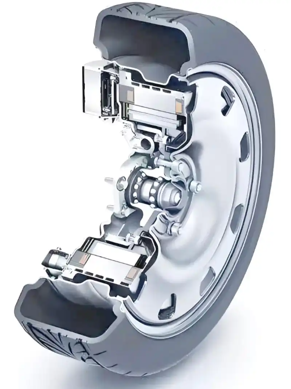
I. Core Structure (From Inside to Outside)
| Component | Core Composition | Function Description |
|---|---|---|
| Stator Assembly | Silicon steel sheet laminated core, three-phase winding, insulating bobbin, Hall sensor | Fixed on the main shaft; three-phase AC power generates a rotating magnetic field, and the Hall sensor feeds back rotor position |
| Rotor Assembly | Permanent magnet (alternating N/S poles), rotor yoke/hub shell, rotating shaft | Rotates integrally with the hub; the permanent magnet cuts the stator magnetic field to generate torque, with surface-mounted/embedded magnetic steel as the main type |
| Reduction System | Planetary gear set (sun gear, planet gear, ring gear, planet carrier) | The single-stage transmission ratio ranges from 4:1 to 5:1, and the two-stage can reach more than 20:1, which increases low-speed torque and adapts to scooter starting and climbing |
| Support and Sealing | Main shaft, deep groove ball/angular contact bearing, oil seal/sealing ring, side cover | The main shaft is fixed on the frame; the bearing ensures low-friction rotation, and the sealing achieves IP54/IP65 protection to prevent water and dust from entering |
| Control and Sensing | Lead wire, resolver/Hall device, temperature sensor | The lead wire transmits power and signals; the sensor monitors speed/position/temperature in real time to ensure precise speed regulation of the controller |
| Brake Integration | Drum/disc brake | Installed coaxially with the hub, providing driving and parking braking with a compact structure |
II. Full Production Process
1. Precision Component Prefabrication
- Stator core: High-speed blanking of silicon steel sheets → automatic lamination (flatness control ≤0.05mm) → laser welding/riveting fixation → insulation treatment (varnish dipping/coating).
- Winding manufacturing: Winding of three-phase coils by automatic winding machine → slot embedding → shaping → varnish dipping and curing (VPI vacuum pressure impregnation) → insulation and DC resistance testing.
- Rotor processing: CNC turning/stamping of hub shell → magnetic steel positioning and bonding (anaerobic adhesive) → dynamic balance weight removal (residual unbalance ≤5g·cm).
- Planetary gear: Manufactured by powder metallurgy/high-strength engineering plastic with precision finishing of tooth surface to ensure meshing accuracy and wear resistance life.
2. Stator and Rotor Manufacturing
- Stator: Winding embedding into core → end shaping → lead wire welding → Hall sensor installation → potting and sealing of wire outlet → insulation withstand voltage test (AC 1500V, no breakdown for 1min).
- Rotor: Magnet charging → surface-mounted/embedded into rotor yoke → magnetic flux and polarity detection after curing → shaft press-fitting and bearing hot sleeve → dynamic balance correction.
3. Assembly Integration (Key Processes)
- Main shaft positioning → stator press-fitting (coaxiality guarantee ≤0.02mm) → bearing preload (closed-loop control of force-displacement curve).
- Planetary gear set assembly → docking with rotor/hub shell → adjustment of tooth side clearance and preload force.
- Stator-rotor assembly: Guided by laser ranging + machine vision, control air gap uniformity (deviation ≤0.03mm) to avoid vibration and noise caused by unbalanced magnetic pull.
- Side cover and sealing: Gluing (UV adhesive/silicone adhesive) → side cover press-fitting → bearing preload detection → bolt tightening → air tightness test (0.2MPa, no leakage for 30s).
- Lead wire and sensor assembly: Welding of power/signal wires → heat shrink tube sleeving → plug-in fixation → continuity test.
4. Testing and Aging
- Performance test: No-load/load test (measuring speed, torque, efficiency, power) → locked-rotor test → back electromotive force detection → Hall phase angle calibration.
- Environmental and durability test: High and low temperature cycle (-20℃~60℃) → salt spray test → waterproof and dustproof test (IP grade) → 100h aging operation, monitoring temperature rise and attenuation.
- Factory inspection: Dynamic balance recheck → full appearance inspection → laser coding (traceability information) → packaging and warehousing.
III. Key Process Control Points
- Air gap uniformity: Adopt online monitoring with vision + laser, and the air gap deviation after assembly is ≤3% to reduce noise and vibration and improve efficiency.
- Bearing press-fitting: Servo press + closed-loop control of force-displacement curve to avoid abnormal noise/wear caused by over-pressing damage or insufficient preload.
- Dynamic balance: The dynamic balance accuracy of the rotor assembly reaches G2.5 grade, and the residual unbalance is ≤2g·cm to prevent high-speed jitter.
- Insulation and sealing: The insulation resistance of the winding is ≥100MΩ, with a withstand voltage of AC 1500V/1min; the sealing part adopts double oil seals + potting to ensure IP protection.
IV. Typical Failures and Process Improvements
Common Failures
Magnetic steel falling off (insufficient bonding strength), winding burnout (insulation defects), bearing abnormal noise (improper preload), uneven air gap (assembly deviation).
Improvement Directions
Adopt two-component epoxy adhesive + buckle fixation for magnetic steel; use VPI process for windings to improve insulation reliability; introduce SPC statistical process control for bearing press-fitting; equip the assembly line with online visual inspection to 100% screen air gap deviation.
V. Structure and Process Selection Suggestions
| Application Scenario | Structure Selection | Process Focus |
|---|---|---|
| Urban commuter scooter | 250W~500W, single-stage planetary reduction, drum brake | IP54 protection, cost control, mass production |
| Mountain/heavy-duty scooter | 500W~1200W, two-stage planetary reduction, disc brake | Strengthen the strength of magnetic steel and gears, VPI varnish dipping, IP65 sealing |
| High-speed scooter | ≥1200W, water cooling, vector control | G1 grade dynamic balance, bearing preload optimization, temperature monitoring |
VI. Summary
The core of structural optimization for scooter hub motors lies in the balance between power density and reliability. Production needs to ensure consistency with automated equipment, adopt online detection and SPC control for key processes, and realize full-process traceability, ultimately achieving the application goals of “low-speed high torque, high efficiency and energy saving, and long service life”.